Table of Contents
ToggleThermionic Valves - A guide to where we are Heading
While Part 2 explored modern power semiconductors that dominate today’s high-power world, Part 3 steps back in time to their glowing ancestors — the thermionic valves (vacuum tubes). These remarkable devices powered the electronics revolution for over half a century and still hold a special place in audio, radio, and niche applications.
My Personal Connection As a former merchant navy radio officer (“sparky”) in the 1980s, I spent many hours maintaining and operating tube-based equipment on ships. Even as transistors took over, many maritime radios and radar systems still relied on tubes for their robustness in harsh conditions. That hands-on experience left me with lasting respect for these glowing glass wonders.
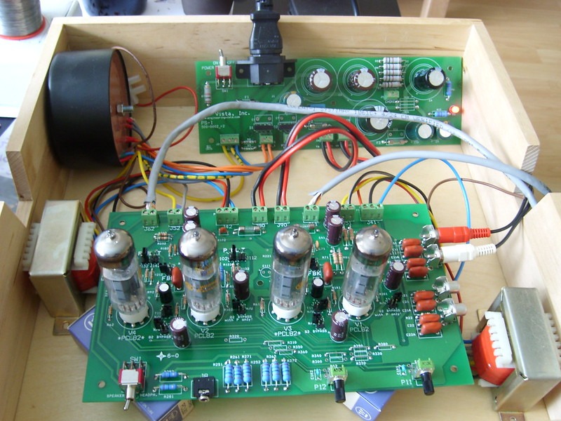
When Did It All Start and Why?
The story begins in the late 19th century. Scientists were investigating electricity and the behaviour of heated metals in a vacuum. The key breakthrough came with the discovery of the thermionic effect (also called the Edison Effect). This enabled the development of the first electronic components that could control the flow of electrons — paving the way for radio, radar, television, and early computers.
Timeline Overview
- 1880s: Edison observes the thermionic effect.
- 1904: First practical diode.
- 1906: Triode (the birth of amplification).
- 1910s–1930s: Tetrodes, pentodes, and beam tetrodes refine performance.
- 1940s: Cavity magnetron revolutionises radar during WWII.
- 1950s–1960s: Peak usage, then rapid replacement by transistors.
- 1970s–Present: Tubes retreat to niche high-end audio, guitar amps, and specialised industrial/RF uses.
The Thermionic Effect
When a metal filament is heated in a vacuum, it “boils off” electrons (thermionic emission). These free electrons can be attracted to a positively charged plate, creating a controllable current — the foundation of all vacuum tubes.
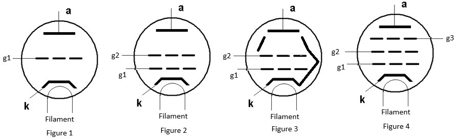
The Diode
Inventor: John Ambrose Fleming (1904), building on Edison’s work.
Pros over Semiconductor Diodes: Handles very high voltages and power; extremely rugged in harsh environments; naturally rectifies high-frequency signals well.
Cons: Requires high voltage and heating power (filaments consume watts); bulky; generates significant heat; shorter lifespan due to filament wear.

The Triode
Inventor: Lee de Forest (1906) — he added a control grid between cathode and anode.
Pros: First device capable of amplification; enabled radio broadcasting and long-distance communication.
Cons: High inter-electrode capacitance (limited high-frequency performance); relatively low gain; prone to microphonics (sensitive to vibration).
The Tetrode
Inventor: Walter Schottky (1919) added a screen grid.
Pros: Higher gain and better high-frequency performance than the triode.
Cons: Secondary emission from the anode caused instability (the “tetrode kink”).
The Beam Tetrode
Inventors: Developed by British engineers at EMI/Marconi-Osram (1930s), popularised by the 6L6 in the USA.
Pros: Overcomes tetrode issues with beam-forming plates; excellent power handling and efficiency; lower distortion in audio applications.
Cons: Still requires careful circuit design; larger size than later semiconductors.
The Pentode
Inventor: Bernard Tellegen (1926, Philips).
Pros: Suppresses secondary emission with a suppressor grid; very high gain; excellent for RF amplification and audio power stages.
Cons: More complex construction; still power-hungry and heat-producing.
Key Concepts: Biasing and Valve Characteristics
Proper biasing is essential for tubes to operate correctly. Common methods include:
- Cathode Bias (self-bias) — simple and popular in audio amplifiers.
- Fixed Bias — uses a negative voltage supply for more control and higher efficiency.
- Grid Bias variations for different operating classes (Class A, AB, B).
Biasing sets the quiescent operating point and prevents distortion or tube damage.
Transconductance (gm) and Voltage Gain
A crucial parameter is gm (transconductance), measured in mhos (or Siemens). It indicates how effectively the control grid voltage influences the anode current. Higher gm generally means higher possible voltage gain in an amplifier stage.
Unlike BJT transistors (which are current-controlled devices), vacuum tubes are voltage-controlled devices — very little current flows into the grid, similar to how FETs and MOSFETs operate.
This voltage-control characteristic makes tubes (and FETs) excellent for high-input-impedance circuits and gives them a particular sonic quality that many audiophiles prefer.
Cavity Magnetron
Inventors: John Randall and Harry Boot (University of Birmingham, 1940).
Why it was invented: To produce high-power microwave signals for radar during WWII.
Where it is mostly used: Radar systems (aircraft, naval, weather), microwave ovens, and some industrial heating.
Pros vs Semiconductor versions: Can generate enormous peak power levels (hundreds of kilowatts) at microwave frequencies.
Cons vs Semiconductor versions: Inefficient (produces a lot of heat); bulky; requires high voltage; now largely replaced by solid-state GaN and other microwave devices in modern systems.
Popularity in Guitar Amplifiers
Tubes remain king in high-end guitar amps because of their unique sound characteristics.
When pushed into overdrive, tubes produce rich even-order harmonics and a pleasing, musical distortion (soft clipping) that solid-state amps struggle to replicate naturally.
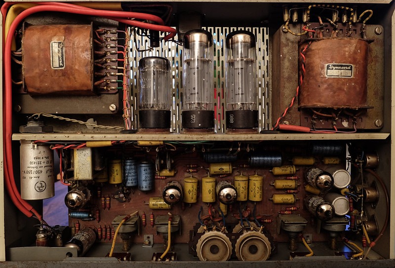
Icons like the Fender, Marshall, and Vox amps owe their legendary tone to tubes such as the EL34, 6L6, and 12AX7. Many guitarists still prefer the dynamic “feel” and compression that tubes provide.
Are Tubes Still Being Manufactured?
Yes, though in much smaller volumes. Major producers include: • Electro-Harmonix (Russia/USA) • JJ Electronic (Slovakia) • New Sensor (Russia) • Shuguang and Psvane (China) • Western Electric (reissues in the USA)
Specialist factories continue production for audio, military, and industrial markets
Tubes to Look Out For
12AX7 / ECC83 — The most popular preamp tube…
EL34 / 6CA7 & 6L6 — Classic power tubes…
EL84 / 6BQ5 — Compact power pentode, beloved in smaller guitar amps (e.g., Vox AC15, many boutique builders) for its sweet, chimey tone and lower power output.
2A3 / 300B — Highly sought-after for single-ended hi-fi…
Common Reasons for Tube Failure
The most frequent causes are filament burnout (especially from voltage surges or age), cathode depletion (loss of emission over thousands of hours), internal shorts, and mechanical damage from vibration or shock.
Gentle warmup and proper biasing greatly extend tube life. (large amplifiers, transmitters, radar all have standby mode switching off the EHT and just leaving heaters on. Also, timers were used to prevent EHT from being applied until the cathodes were properly heated).
Are Tubes Better Than Semiconductors...?
Yes, in specific applications:
- Audio quality — Many listeners prefer the warm, forgiving, harmonically rich sound.
- High-power RF — Tubes still excel in broadcast transmitters and radar where extreme power levels are needed.
- Ruggedness — Tubes can tolerate higher voltage spikes and radiation better than early semiconductors.
- Repairability — Easier to replace a single glowing tube than diagnose a failed SMD board.
However, semiconductors win on efficiency, size, reliability (no filament burnout), power consumption, and cost in almost every other area.
Last and not least – the Cathode Ray Tube.
No discussion of thermionic valves would be complete without the Cathode Ray Tube — perhaps the most recognisable vacuum tube of the 20th century. CRTs operated at very high voltages (often 15–30 kV) and required careful safety handling due to the risk of soft X-ray radiation if shielding or circuits were compromised.
Main Types and Evolution • Monochrome CRTs: Used electrostatic (capacitive) or electromagnetic (deflection coil) systems for beam control. Simple and reliable for oscilloscopes and early radar/TV. • Colour CRTs:
- Shadow Mask Delta — Early triangular arrangement of red, green, and blue phosphor dots.
- Inline Tubes — Phosphor stripes in vertical lines for simpler convergence.
- Lawrence Tube (Chromatron) — Used colour-switching grids.
- Sony Trinitron (1968) — The standout design with an aperture grille (vertical wires instead of a shadow mask). It delivered brighter, sharper pictures with better contrast and less distortion. Many consider it the pinnacle of CRT technology.
Why the Horizontal Stabilising Wire? In Trinitron and some aperture-grille tubes, a thin horizontal stabilising wire (or wires) keeps the fine vertical grille wires taut and prevents vibration or deformation, ensuring consistent image quality.
Conclusion
Vacuum tubes lit the way for the entire electronics industry…
From my own workbench, from an experimentation viewpoint and more, I can highly recommend the Russian 6J1P or 6J2P pentodes for anyone wanting an easy and low-voltage entry into tube electronics.
These are affordable, readily available, and excellent for building simple “starved cathode” preamplifiers that run on low plate voltages (often under 50V). They offer a gentle introduction to tube sound without the dangers of high-tension (EHT) supplies, making them ideal for beginners and experimenters.
In Part 4 we’ll bring the story full circle with modern FinFET and Gate-All-Around transistors…
⚠️ IMPORTANT SAFETY DISCLAIMER
Working with mains voltage (230V AC in South Africa or 120V AC in the USA and other regions) is extremely dangerous and can result in severe electric shock, burns, fire, or death.
This article is for educational and informational purposes only. If you are not a qualified electrician or have no professional training and experience in high-voltage electronics, do not attempt to build, modify, or troubleshoot any circuits connected to mains power.
Always follow local electrical regulations and standards (e.g., SANS 10142 in South Africa). Use proper isolation transformers, residual current devices (RCDs/GFCIs), and safety equipment. When in doubt, consult or hire a licensed professional.
Parts-Ring and the authors accept no liability for any damage, injury, or loss resulting from the use or misuse of information in this article.
Further Reading
- Power Vacuum Tubes Handbook – Jerry C. Whitaker (Author) .pdf 19MB
- Saga of the Vacuum Tube – Gerald F.J. Tyne (Author) .pdf 20MB Research Associate
Smithsonian Institution – Copyright © 1977 by Gerald F. J. Tyne - The Vacuum Tube Explained – Tamco Pedals and Amplifiers
- Akai M8 Restoration
- Essential Transistors for Beginners: Must-Have Spares, History & Counterfeit Detection (2026) – Part 1
- Power Switching Semiconductors: Thyristors, IGBTs, GTOs, SIDACs & Wide-Bandgap Devices Explained (2026) – Part 2
- The Arduino Revolution – From Italian Student Project to Global Maker Powerhouse
- My Complete Guide to a Smart Home: What It Is and How It Works – cnet.com
- 5 Websites for smart home enthusiasts – Smashing Hub
- Home Assistant – Home
- DC Blinding Warning: 6mA RDC-DD, Type B RCD & SANS 10142-1 in South Africa
- Solar Panel & Battery Theft in South Africa: The Growing Crisis – And a Simple, Smart Detection Solution
- The Silent Killer in Your EV Charger Installation: Why Your Cheap “ELCB” Could Get Someone Electrocuted (And Why Municipalities Are About to Crack Down)
Technical Research and Image Credits
- Feature Image: MC240 tube amplifier (early version), manufactured by McIntosh Laboratories in 1961
tube cage removed. This file is licensed under the Creative Commons Attribution-Share Alike 4.0 International license. Author Sebastian Nizan - DIY Tube amplifier – test setup. CC BY-NC-SA 2.0 Author Wim Fournier (Flickr)
- Dynacord Eminent. CC BY-NC 2.0 Author Stephan Harmes
- Vacuum Tube Diode. This file is licensed under the Creative Commons Attribution-Share Alike 3.0 Unported license.
- Research: Technical assistance and cross-referencing provided by X’s xAi Grok and Google’s Gemini Ai model.
- Editorial: All case study data, circuit designs, and final editorial decisions are the sole responsibility of the author to ensure technical accuracy