The global regulatory response to “DC blinding” has created a clear divide between legacy electrical thinking and the new “power electronics” era. While each region uses different terminology—RCDs in the UK and Australia versus GFCIs and CCIDs in the USA—the physics they are fighting remain the same: 6mA of smooth DC is the “kill switch” for traditional safety devices.
Table of Contents
Toggle1. United Kingdom: The IET Lead
In the UK, BS 7671 (Amendment 2) has effectively made Type AC breakers obsolete for any modern electronic load. For EV charging, the law is rigid: you must use a Type B RCD unless the charger itself has a certified RDC-DD (Residual Direct Current Detecting Device) that trips at 6mA. This “6mA rule” is the gold standard for preventing upstream blinding, ensuring that even if a car develops a DC fault, the house’s primary safety switch remains functional for the rest of the family.
2. Australia & New Zealand: The "Bollard & Breaker" Approach
Australia’s AS/NZS 3000 (The Wiring Rules) takes a dual-pillar approach to safety, focusing on both physical and electrical resilience. Like the UK, they mandate Type B protection or a 6mA RDC-DD for all Mode 3 EV chargers. However, they go further by strictly regulating the installation environment, often requiring dedicated isolation switches and mechanical protection (like bollards) if the charger is in a high-impact zone. They treat the EV charger not just as an appliance, but as a high-risk power sub-station within the home.
3. United States: The "Smart Appliance" Model
The USA handles blinding through NEC Article 625 and UL 2231-2, which place the safety burden on the EVSE (Electric Vehicle Supply Equipment) rather than just the breaker panel. Instead of an external RCD, US chargers must include an integrated CCID (Charge Circuit Interrupting Device). A CCID5 trips at 5mA of leakage (AC or DC), providing a slightly tighter safety margin than the European 6mA standard. This ensures that the protection is “active” and microprocessor-controlled, rather than relying on the passive magnetic coils found in old-school breakers.
4. South Africa: The Emerging "Section 7.15" Framework
In South Africa, we are currently in the middle of a massive “compliance pivot.” While legacy installations still lean on the outdated “ELCB” terminology, the SANS 10142-1 Edition 3.2 (2024) has introduced Section 7.15, which moves DC installations and EV infrastructure into the Normative (legally binding) category. By aligning with international IEC codes, South Africa is finally closing the loop that allowed “cheap” Voltronic-style installs to bypass safety logic. The message from local authorities is becoming clear: if your equipment manual specifies Type B protection, it is no longer an “option”—it is a legal requirement for a valid CoC.
DC Blinding South Africa – Practical Charger Landscape (2026)
Local availability reflects the global split: premium chargers ship with integrated 6 mA RDC-DD (IEC 62955) protection, allowing simpler Type A upstream devices and lower install costs. Budget or older units often require full Type B RCD protection at the DB to guard against smooth DC leakage blinding household safety devices.
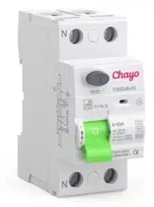
Popular compliant home EV chargers available in South Africa (2026):
- myenergi Zappi (v2/v2.1) — Solar-optimised favourite (built-in 6mA DC protection).
- Wallbox Pulsar Plus / Pulsar Max — Compact and smart (supports RDC-DD).
- Suntree EV Charging Station — Built-in Type B option.
- Other strong options: Easee Home, Schneider EVlink, Growatt, etc.
Standalone RDC-DD Modules – The DIY / Retrofit Reality in South Africa
Yes — manufacturers produce affordable standalone RDC-DD modules (e.g. Ivy Metering MD0630STA series and similar IEC 62955-compliant units) that can be installed on the same DIN rail as a standard Type A RCD or RCBO. These modules detect smooth DC ≥6mA and provide a signal to trip a contactor or breaker.
This modular approach gives electricians (and unfortunately some home DIYers) a cheaper alternative to a full Type B RCD. The sensor itself is relatively simple and low-cost, but the complete assembly still requires proper wiring, a suitable contactor, self-test functionality, and correct integration.

- Actuator lever – used to manually trip and reset the circuit breaker. Also indicates the status of the circuit breaker (On or Off/tripped). Most breakers are designed so they can still trip even if the lever is held or locked in the “on” position. This is sometimes referred to as “free trip” or “positive trip” operation.
- Actuator mechanism – forces the contacts together or apart.
- Contacts – allow current when touching and break the current when moved apart.
- Terminals
- Bimetallic strip – separates contacts in response to smaller, longer-term overcurrents
- Calibration screw – allows the manufacturer to precisely adjust the trip current of the device after assembly.
- Solenoid – separates contacts rapidly in response to high overcurrents
- Arc divider/extinguisher
Important South African Warning:
While technically compliant when done correctly (certified components + documented on the CoC), these DIY-style installs are where most problems occur. Incorrect pairing, missing self-testing, poor reset mechanisms, or non-certified modules will fail inspection and can leave the installation unsafe. With the rise of online marketplaces, many “budget” solutions are already appearing in South African garages — often without proper certification. Always use a registered electrician and insist on IEC 62955 certification for any RDC-DD device.
General SA Installation Notes (per SANS 10142-1:2024):
- Dedicated circuit (typically 6–10 mm² cable for 32 A).
- Surge protection strongly recommended.
- For chargers without built-in 6 mA RDC-DD → install upstream Type B RCD or a properly engineered Type A + standalone RDC-DD combination.
- With certified built-in RDC-DD → Type A often suffices.
- Always follow the charger’s Declaration of Conformity and manufacturer instructions for a valid CoC. CoC inspectors are increasingly strict on DC fault handling.
Scope of 7.15 DC Installations
This section addresses DC installations (up to 1 500 V DC, as per the overall scope of the standard). In the 2024 edition, DC requirements have been strengthened and made more explicitly normative (mandatory “shall” requirements) to support the rise in solar PV, battery storage (BESS), telecom power, and other DC systems. It previously had more informative elements in older editions.
Key subsections (structure consistent across recent editions):
- 7.15.1 Selection of equipment and circuits
- All equipment, protection devices, cables, and components must be rated and suitable for DC operation at the specific voltage and current (polarity, arc interruption, etc.). AC-rated devices are generally not acceptable for DC without verification.
- Circuits must account for DC-specific factors like higher fault currents in some cases, no zero-crossing (harder arcing), and voltage drop (≤ 5% generally, or per manufacturer).
- 7.15.2 Earthing
- For earthed DC systems (one polarity earthed, commonly negative or 0V in telecom), specific bonding rules apply.
- Requirements for earthing terminals, electrodes if needed, and bonding of exposed conductive parts.
- Floating (unearthed) DC is often preferred for PV/BESS in newer guidance, but earthed systems have strict rules.
- 7.15.3 Overcurrent protection
- DC-rated fuses or circuit-breakers (e.g., gPV fuses for PV. Characteristics below).
- Protection against overload and short-circuit, considering reverse currents in PV arrays, etc.
- 7.15.4 Disconnection (see also 6.9)
- All poles (positive and negative in unearthed systems, or live conductors in earthed) must be disconnected where required.
- Switch-disconnectors rated for DC.
- 7.15.5 Distribution boards
- DC-specific DBs or compartments, with proper separation from AC, labelling, and IP ratings as needed.
Characteristics: gPV Fuses
- Purpose: They provide “full-range” protection (g = general purpose), meaning they can break any current from the lowest melting current up to the rated maximum short circuit.
- DC Voltage Rating: Engineered for high DC voltages commonly found in modern solar arrays, usually rated for 1000V DC or 1500V DC.
- Fast Response: Designed to blow quickly when overcurrent is detected to prevent damage to sensitive photovoltaic equipment.
- Standards: Comply with IEC 60269-6 and UL 248-19 standards specifically for solar PV applications.
- Appearance: Commonly available in cylindrical forms (like 10×38 mm, 14×51 mm) or NH knife-blade style for larger applications.
Why They Are Different from Normal Fuses:
Unlike standard industrial gG (general purpose) fuses, gPV fuses are optimized for the unique operating conditions of solar power: low fault current levels, high environmental temperatures, and high DC voltage, ensuring safety and preventing long-term damage to PV modules
Further Reading
- Viox – Understanding RCCB Requirements for EV Charging. The DC Fault Current Problem
- Viox – DC MCB
- Tongou – RCD Class B
- Online Parts – The Silent Killer in Your EV Charger Installation: Why Your Cheap “ELCB” Could Get Someone Electrocuted (And Why Municipalities Are About to Crack Down)
- Online Parts – The State of EVs in South Africa 2026: Challenges, Realities & Smart Solar Solutions
eFIXX – The Complete Guide to MCBs – Miniature Circuit Breakers
Technical Credits & Research
- Visuals: Image assets generated by Google’s Gemini AI and PicsArt
- Featured Image: TKT is a manufacturer and supplier of commercial EV chargers in China. This file is licensed under the Creative Commons Attribution-Share Alike 4.0 International license. Author Tank.xing
- Miniature Circuit Breaker (Hager C10). This file is licensed under the Creative Commons Attribution-Share Alike 4.0 International licence Author Marco-279
- Research: Technical assistance and cross-referencing provided by Grok xAI and Gemini.
- Editorial: All case study data, circuit designs, and final editorial decisions are the sole responsibility of the author to ensure technical accuracy.