Table of Contents
ToggleSingle Sideband Transmitters & Receivers - Pure Innovation
Radio communication has always intrigued me, as with the enthusiasts of the international Amateur Radio League. Having worked as a “Sparky” in the 1980s for Safmarine, a South African company which owned a fleet of merchant vessels, I thought it may be a great idea to flash back many decades to show the innovation and perseverance of the pioneers in this fantastic scientific field.
I’ll kick off by introducing you, the reader, to the timeline that charts the development of Single Sideband in transmitters and receivers through the last 110 years. The main focus is not the 1980s onward (when Inmarsat began to dominate merchant-ship communications), but the long technical road that made SSB the efficient HF workhorse it became.

Early Foundations & Mathematical Discovery (1910s–1920s)
1915: Mathematical Proof John Renshaw Carson of AT&T mathematically proved that a standard AM signal contains redundant data in its carrier and two sidebands. He showed that a single sideband can carry the entire audio signal.
1923–1927: First Commercial Transatlantic Service AT&T and the British General Post Office established the first successful long-wave SSB voice transmission between New York and London. The commercial service opened officially on 7 January 1927.
Transmitters were located at Rocky Point, Long Island (USA) and Rugby, England. Receiving stations were at Houlton, Maine and Cupar, Scotland. The operating frequency was around 60 kHz (long-wave). Why 60 kHz? At the time, high-power short-wave technology was still immature, and long-wave ground-wave propagation offered more reliable day-and-night coverage across the Atlantic. The transmitters were massive — water-cooled valves delivering tens to hundreds of kilowatts. Early generation used high-level balanced modulators followed by very large, carefully designed filters (often multi-section LC or early crystal-based arrangements) to reject the unwanted sideband. The power savings over conventional double-sideband AM were already dramatic, which is exactly why the telephone companies adopted it: electricity bills for continuous high-power carriers were crippling.
Moving to Shortwave & Filter Innovations (1930s–1950s)
1930s: The Move to HF Engineers successfully adapted SSB for the short-wave (HF) bands. This opened reliable long-distance international telephone links, but the equipment remained complex and expensive.
Why was SSB not widely used in World War II? Although the theory and some laboratory equipment existed, practical military radios of the 1940s prioritised simplicity, ruggedness and mass production. SSB required extremely stable oscillators and sharp, temperature-stable filters — technology that was still bulky, delicate and difficult to manufacture in wartime quantities. AM and CW (Morse) gear could be built quickly, operated by less-trained personnel, and still functioned under combat conditions. Full military adoption had to wait until the post-war years when mechanical and crystal filter technology matured.
1947–1950s: The Collins Revolution and Military/Amateur Adoption Art Collins and the Collins Radio Company developed high-precision mechanical filters. These allowed radios to separate sidebands cleanly without the bulky, unstable LC filters of earlier designs. Strategic Air Command adopted SSB for long-range bomber communications in the mid-to-late 1950s. Amateur radio operators rapidly followed, proving SSB’s superiority over AM in crowded bands.
The massive 500 kW AM transmitters used by Commercial Radio Stations
1. The Machine and Its Era The most famous example was the WLW 500 kW transmitter near Cincinnati, Ohio, which went on air in May 1934 and operated at full power until 1939. It remains the only AM broadcast transmitter in the United States ever licensed for regular 500 kW operation. Built as a joint effort by RCA, General Electric and Westinghouse during the depths of the Depression, it was pure industrial-scale radio engineering of the mid-1930s.
2. The Power Stage The final amplifiers and modulators ran at approximately 12,000 volts plate voltage. The transmitter used around twenty RCA UV-862 water-cooled triodes — massive tubes roughly five feet tall, each capable of 100 kW anode dissipation. These were classic water-cooled transmitting triodes (not beam tetrodes); the anode formed the outer structure and sat in a water jacket. Cooling water flowed at hundreds of gallons per minute, with an outdoor spray pond dissipating the enormous heat. Filament supplies alone required thousands of amperes.
3. The Modulation Transformers High-level plate modulation was used, so the audio power had to be injected in series with the 12 kV plate supply. This required two enormous Westinghouse modulation transformers. Each unit weighed approximately 35,700 to 37,000 pounds (roughly 16–17 tonnes), stood about 10 feet high, and contained 725 gallons of oil. They had to pass the full DC plate current of the final amplifiers while cleanly handling audio from 30 Hz to 10 kHz at power levels of hundreds of kilowatts. These transformers remain one of the most tangible symbols of just how physically monumental high-power AM broadcasting was in that era.
The above comes from my own research aligned with xAi. I recalled an image where a tube could be opened and serviced, preferable while there was no DC.😁
In my time as a radio guy we often used to listen to BBC for a few minutes before Radio Moscow would kick in, totally overriding BBC’s signal. Now think about this, this was not a skip but pure power – I say this because skips often would suffer from signal fading in and out. Radio Moscow was just deafening.
Solid-State, Synthesizers, and Maritime Laws (1960s–1980s)
1970s: The Marconi Apollo & Solid-State Era Companies such as Marconi introduced highly stable receivers (the Apollo being a classic example) using quartz crystal filters and early frequency synthesizers. This largely eliminated the manual drift that had plagued earlier equipment.
1977–1982: The ITU Maritime Mandate The International Telecommunication Union mandated that maritime mobile services in the HF bands switch from AM to SSB. By the early 1980s the transition was largely complete. On 2182 kHz the regulations moved away from old double-sideband AM, standardising on A3H (full-carrier SSB) for emergency compatibility and direction-finding, and A3J (suppressed-carrier) for normal traffic.
Digital Signal Processing & Satellite Shifts (1990s–2010s)
Physical ring modulators and crystal filters gradually gave way to Digital Signal Processing. Audio was converted to numbers and the carrier suppressed mathematically. In 1999 GMDSS became fully operational, replacing the mandatory voice watch on 2182 kHz with automated satellite alerts and Digital Selective Calling, although SSB remained a legal backup requirement. By the 2010s Software Defined Radios had become the industry standard.
The Modern Era: Digital SSB and Legacy Integration (2020–2026)
2020: Hybrid Digital Modes Legacy SSB bands saw massive integration with digital voice codecs such as FreeDV and highly efficient digital data modes (FT8/FT4). These allow signals to be decoded even when buried deep in radio noise — often 10–20 dB below the noise floor that would render conventional SSB unreadable.
2024: AI-Enhanced Noise Blanking Manufacturers began integrating machine-learning algorithms directly into commercial and military SDR transceivers. These systems can isolate human voice from HF atmospheric noise, static crashes and interference in real time on standard A3J links, something traditional noise blankers struggled with.
2026: Deep Software Integration & Cloud Routing Modern maritime and aviation emergency backup networks now use compact software-defined architectures. Physical radio rooms are increasingly supplemented (or replaced) by remote, cloud-linked SDR receivers that can monitor thousands of SSB frequencies simultaneously, applying software algorithms instead of physical filters.

As an Amazon Associate, Parts-Ring earns from qualifying purchases.
Single Sideband and the Advantages over Full Amplitude Modulation
Your SSB signal, especially the fully suppressed-carrier version, is like a hot needle through butter as opposed to the double-sideband amplitude-modulated signal’s battering-ram effect — there can never be enough power.
Power reality check – Conventional 100 % modulated AM
- The carrier contains approximately two-thirds of the total average power (or exactly half the peak envelope power).
- The two sidebands together share the remaining one-third (each sideband roughly one-sixth of total average power).
- A 1 kW carrier AM transmitter therefore needs a modulator capable of delivering hundreds of watts of audio power and produces a PEP of 4 kW, yet only a fraction of that power actually carries intelligence.
SSB A3J (suppressed-carrier, modern J3E)
- Virtually all of the peak envelope power is concentrated in the single information-bearing sideband.
- No continuous carrier, no redundant sideband. The result is dramatically higher effective talk power for a given amplifier size and power supply — exactly why a well-operated 100–150 W PEP SSB signal routinely outperforms a much larger AM transmitter on HF. That is the “needle through butter” elegance I refer to.
How little audio power does A3J really need?
Take a typical maritime HF transmitter rated at 1.5 kW PEP in A3J (fully suppressed carrier) mode, running into a Class AB linear amplifier. Because the SSB signal is generated at low level in a balanced modulator and then amplified linearly, the audio/modulator stages only have to produce a few watts — typically less than 5 W, and often only 1–2 W of actual audio power.
Contrast that with conventional high-level AM plate modulation. A 1.5 kW carrier would already need roughly 750 W of audio power for 100 % modulation. Scale it up to the old high-power broadcast transmitters (BBC, SABC and others) that ran 500 kW carriers: those required approximately 250 kW of clean audio power from the modulator just to reach 100 % modulation. That is the real magnitude of the difference. In A3J the “modulator” is no longer a massive high-power audio amplifier fighting to push the carrier around — it is a low-level circuit that merely shapes a clean SSB signal before the linear stages do all the heavy lifting. This is why a 1.5 kW SSB transmitter can be far lighter, cooler-running, and more power-efficient than an equivalent AM machine.
Schematic of a Ring Modulator
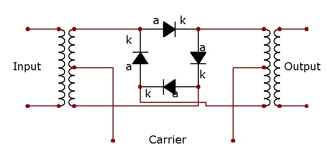
Wikipedia: Schematic diagram of a ring modulator, showing ring of diodes. Read the article here on Ring Modulation. Note —often called a double-balanced modulator—because it suppresses both the input carrier and the modulating signal from the output.
Circuits that Produce the Three Classic Modes
- A3H / H3E (SSB with full carrier) A balanced modulator creates a double-sideband suppressed-carrier signal. One sideband is removed by a sharp filter, after which a controlled amount of carrier is deliberately re-inserted. The residual carrier allows older envelope-detector receivers to demodulate the signal and also assists direction-finding.
- A3A / R3E (SSB with reduced or pilot carrier) Similar generation path, but only a low-level pilot carrier is left in the transmission. This provides a frequency reference for automatic frequency control or easier tuning without sacrificing most of the power advantage of full suppression.
- A3J / J3E (fully suppressed carrier) Pure double-sideband suppressed-carrier from a balanced modulator, followed by a high-rejection crystal or mechanical filter (or generated by the phasing or Weaver method). This is the classic modern HF SSB voice mode used by amateurs, maritime stations and most professional HF users.


As an Amazon Associate, Parts-Ring earns from qualifying purchases.
Modulators, Filters and Synthesisers
- The Filter Sequence Early SSB relied on large LC filters. Collins introduced mechanical filters (resonant metal discs and coupling rods) that delivered steep skirts in a compact package. These were followed by quartz crystal lattice filters, which offered even better temperature stability and narrower bandwidths. Later, Surface Acoustic Wave (SAW) filters appeared, especially useful at higher intermediate frequencies. Each generation improved selectivity, reduced size and improved temperature stability — critical for shipboard and airborne use.
- Modulators and Power Waste In conventional AM the modulator had to handle high power — often plate or collector modulation of the final amplifier. Roughly two-thirds of the transmitter’s output power sat in the unchanging carrier. The balanced modulator (ring modulator or similar) solved this for SSB by using two signals of opposite phase so that the carrier components cancelled, leaving only the sidebands. This low-level generation meant the high-power linear amplifier only had to amplify the useful information.
- Frequency Synthesisers and the PLL Early SSB equipment used switched crystals or crystal-multiplier chains. Frequency synthesizers changed everything. The Phase-Locked Loop (PLL) became the de-facto standard from the 1970s onward. A stable reference crystal is compared with a voltage-controlled oscillator that has been divided down; the loop locks the VCO to an exact multiple of the reference. This delivered the frequency stability and channelisation that modern HF operation demands, eliminating the drift that earlier free-running oscillators suffered.
In Conclusion
Just in case we have some wise ass thinking that conventional radio is all but dead in 2026, think again. 😂😂🤣
Looking back to the early 1900s one can see the massive injection of SSB into the communication systems of merchant ships, aviation and amateur radio. Sadly, amateur radio has lost a lot of traction and the romance of communicating via short-wave SSB has diminished as we move to SDR and digital protocols.
Trust me when I say that in a natural disaster, SSB and CW (Morse Code) may still be the ultimate life saver. Real-world examples include:
- Hurricane Katrina (2005) — more than a thousand amateur operators provided critical health-and-welfare and logistical traffic when cellular and landline systems collapsed.
- Hurricane Maria in Puerto Rico (2017) — amateur radio was often the only functioning communication link off the island for days; operators used HF SSB and Winlink digital messaging to relay emergency traffic for the Red Cross and local authorities.
- Numerous earthquakes, wildfires and blackouts worldwide where HF SSB nets have carried life-saving messages when every other system failed.
The “needle through butter” remains as relevant in 2026 as it was when Carson first did the mathematics more than a century ago.
The Filter We Built for Ham Radio Is Now in Every Smartphone
In 1880, Pierre and Jacques Curie discovered that certain crystals vibrate at precise frequencies when stressed with electricity. By the 1950s, amateur radio operators and engineers at Collins Radio in Cedar Rapids, Iowa, had turned that principle into razor-sharp mechanical and crystal filters, the components that finally made single-sideband voice communication practical on crowded shortwave bands. You Tube Channel: The History Archive
Thanks to Richard Morris for sharing this link to the above video with me – this filter, in my days more the Xtal filter, played a massive role in sideband rejection.
Further Reading
- Eeeguide – Introduction to SSB Modulation
- Essential Transistors for Beginners: Must-Have Spares, History & Counterfeit Detection (2026) – Part 1
- Power Switching Semiconductors: Thyristors, IGBTs, GTOs, SIDACs & Wide-Bandgap Devices Explained (2026) – Part 2
- Thermionic Valves & Vacuum Tubes: The Enduring Technology Behind Classic Electronics (2026) – Part 3
- FinFET and Gate-All-Around Transistors: Modern 3D Architectures Powering AI & High-Performance Computing (2026) – Part 4
- How Intel Lost Its Way and How They Are Planning to Make a Comeback.
- The Arduino Revolution – From Italian Student Project to Global Maker Powerhouse
Technical Research & Image Credits
- Featured Image: A view of the radio transmitter room aboard the destroyer HAYLER (DD-997) at 90 percent completion. Enlarged and Colourised by PicsArt.
- TRIO TS-520S, HF transceiver, manufactured in the 1970s and 1980s by the Japanese company Kenwood (formerly Trio). The photo also includes a photo of the nameplate for this transceiver. This file is licensed under the Creative Commons Attribution 4.0 International license. Author Zalasem1
- Research: Technical assistance and cross-referencing provided by X’s xAi Grok and Google’s Gemini Ai model.
- Editorial: All case study data, circuit designs, and final editorial decisions are the sole responsibility of the author to ensure technical accuracy