Table of Contents
ToggleNAD 7100 Repair - Continuation
As mentioned in a previous article we will break down the 7100 here and explain it’s workings, hopefully to make trouble-shooting easier.
Caution: This column has been written for those savvy in electronic repair, those knowing the difference between voltage, current and resistance. High voltages, such as used in the 7100 audio amplifier/receiver are dangerous. The 7100 series amplifier/receiver uses two supply rails +/- 45V or 90V in the audio stage and in the PE stage +/- 72V or 144V DC. In an environment which has not been designed for proper diagnostic checking, proper supervision and/or diagnostics and are not carried out by suitably qualified personnel these voltages can be lethal.
Like most amplifiers or electronic equipment the simplest repair is usually a dead set – this is not necessarily the cheapest repair however because the mains transformer is usually the costliest item on the parts list (usually!).
The NAD 7100 is going to be no different. The NAD 7100 has extensive safety circuitry built in and as long as the user doesn’t put 110 / 220V onto a loudspeaker terminal things should rarely go wrong with the components except for old age taking it’s toll.
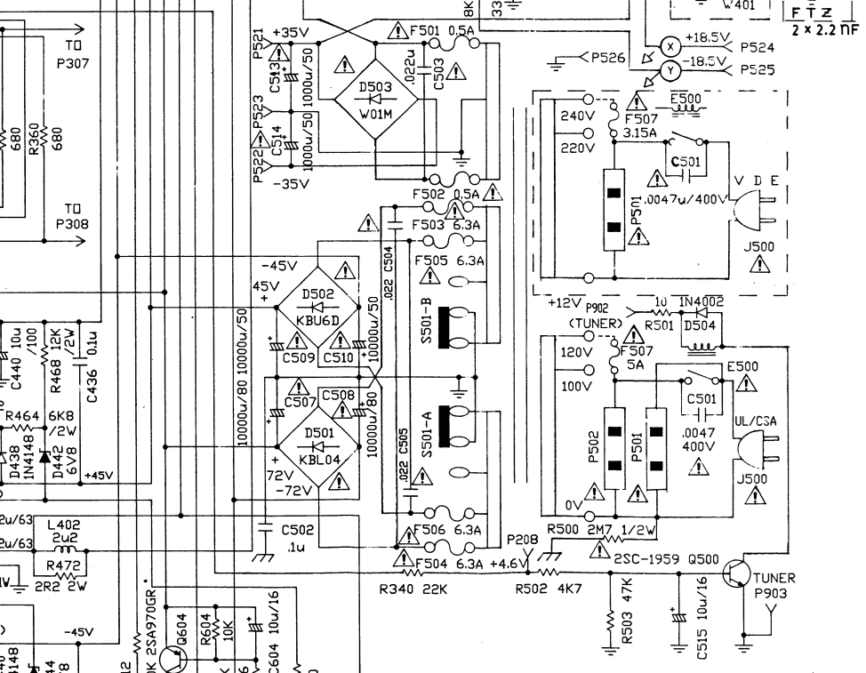
NAD 7100 PSU Schematic – showing +45V / -45V rails
The +/- 45V feeds the output stages. Or does it? Power Envelope and Power on Demand.
How to get sufficient head room and beat the competition.
What is the potential power output of this amplifier? (( (Vcc * 0.707) / Load R ) ^ 2) * Load R or Vcc ^ 2 / 8 * Load R. In this case 253W into a 4 Ohm purely resistive load. Power supply limitations and circuit configuration which includes drive to the output transistors play a role here. According to specification this amplifier can deliver 60W RMS into an 8 Ohm load.
This power supply uses pretty hefty reservoir capacitors (10 000 uFD) of very good quality in the power supply. A loud hum and/or fuses blowing could be cuased by faulty electrolytics or a faulty diode in the bridge rectifiers D501 / D502. Often it is necessary to disconnect the power supply output from the load if trouble-shooting in this area. It will also prevent further damage from occuring. Make sure that you have disconnected properly and not only part of the circuit – do a resistance check.
NAD 7100 Repair The audio amplifier (power amplifier).
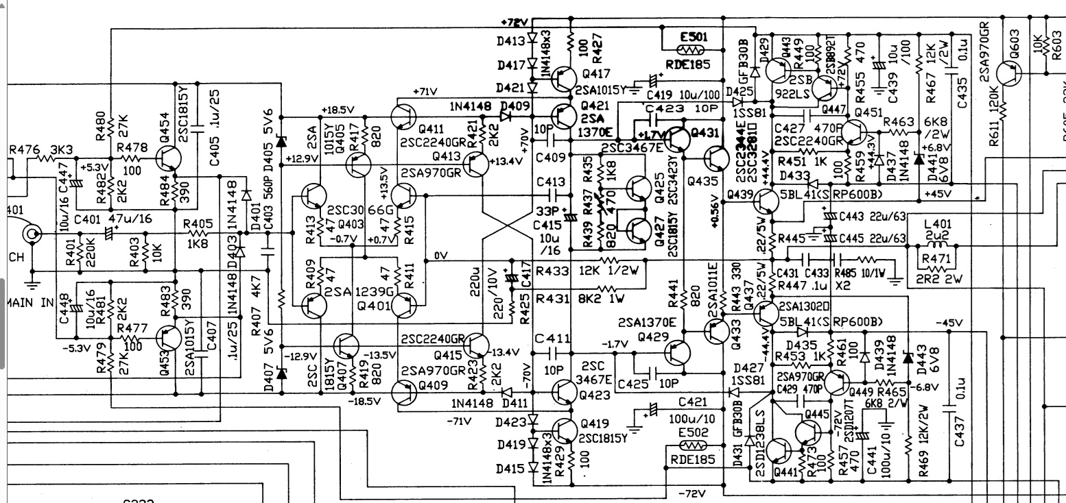
NAD 7100 Power Amplifier Schematic
Click on the audio amplifier schematic to get a better view. We are only showing one channel – tests will be done on the channel that is faulty. The amplifier output stage is formed by Q439 and Q437. The configuration is straight forward: Q431 and Q435 drive Q439 (all NPN) and Q429 Q433 drive Q437 (all PNP). The +/- 45V supply rails are connected to D433 and D435 which feed the output pair.
Bias current is set by R437, Q425 and Q427.
A good starting point for an amplifier which switches on but has no audio out would be first to check that the pre-amplifier is indeed amplifying the input signal – with this amplifier you do have a pre-amp out. Test the output into a known good amplifier. Once you have diagnosed that the problem definitely exists in the power amplifier check the supply rails to the collectors of Q439 and Q437 – check the midpoint voltage (speaker out is as 0V). Check for warmth on the heatsinks – are they even temperature over both output devices. Are both channels warm?
The schematic gives test voltages whilst the amplifier is in idle (quiescent) mode. Getting to these relevant test points is not difficult but ensure that your probes are adequately insulated. Directly coupled amplifier failure is normally catastrophic if you do cause a short, no matter how long you succeed in holding the probe across emitter and collector or base collector or heaven forbid across a capacitor. It is not advisable to bridge electrolytics in an amplifier – it’s a tried and tested check amongst the experienced in television repair – the current surge can cause damage, especially in the small signal path.
It is of consequence to note that the amplifier (almost all) must be balanced for maximum signal amplification without the sine wave being distorted. Small signal transistors can give good voltage readings when in fact they are leaky. I do not believe in the shotgun method of repair (changing all the transistors) because a catastrophic failure of the output pair may have been caused by something not as obvious as a transistor. Look for dry joints around the small signal circuit if the transtor voltages appear normal and the transistors have been tested.
Check zener voltages D441, D443, D407, D405. If there is no voltage between anode and cathode check the current path
Replace C419, C421 – C439, C441 – C417, C415 – C443, C445. Often it is advised to change all electrolytic capacitors, especially where there may be low gain or distortion.
In general..
Power amplifier failure can be caused by it being dropped or physically mishandled without the owner knowing about it. I had a Sansui amplifier which had been dropped – it could not be repaired, the output and driver transistors were all blown. (this was a unit which had been stolen and later retrieved before the new ‘owner’ could test it). Lots of egg on my face – what should have been a simple repair just took up too much time. Initial investigation showed hairline cracks around the input circuitry of the power amplifier stages, around the differential amplifier in fact, right next to a chassis mount. It was not a sophisticated circuit like the 7100 but try as I might I ended up blowing the power transistors again – the test voltages would be normal, bias current normal, temperature luke warm and suddenly the fuses would blow. I never found the cause of this – I just had to walk away and cut my losses. Power amplifiers that have been dropped usually show cracks around any part which has been fastened to the chassis, possibly mains transformer or other heavier components. Bridging with good quality wire is the best fix, insulated or uninsulated. Try to keep as short as possible, running insulated wire across the crack to form a link is the most popular method.
Electrolytic capacitors dry up. Often experienced repair personnel know the cheap capacitor makes from the more expensive and no, not all capacitors are created equal. Pay for the best. Use the correct voltage and temperature rating. SMPSU use 105 deg caps. Don’t put 85 deg C caps in a SMPSU unless it’s for testing purposes only The quickest means of testing amplifiers with low gain is by using an oscilloscope. I knew a technician whom boasted he had never used a scope to conduct a repair. Try that on high frequency video circuits which have low gain. At some stage or other you will find a scope is invariably useful – it is often quicker to use for diagnosis and in small signal circuits is worth it’s weight in gold. Scopes lend themselves to D.C. checks as well as A.C. – not having to make any changes to configuration makes this a very versatile piece of equipment. I’ll also go so far as to say that many DIYers have improved the quality of their cheaper home systems by using a scope. In some cases one can ONLY conduct a repair with a scope, especially when it comes to filters and a.c. measurement. A word of caution here: Be very careful of input grounds. A floating supply which gets grounded by your scope may cause a lot of damage. Know the limitations and if necessary follow the grounding rules applicable to any test equipment. See here – Tektronix information on floating measurements.
Power amplifiers are not usually difficult to fix if you know what to expect when certain components go faulty. Older amplifiers which ‘just fail suddenly’ are often a result of dry-joints, cracked boards and/or electrolytic capacitor failure. Newer amplifiers are in fact very reliable unless the user overdrives the output stage – e.g. into very low impedance loads. Modern equipment however does seem to veer away from using good quality transformers as a means to price cutting.
Cutting corners…
The 7100 designers and manufacturers did not cut corners. Most of the faults advertised on the web cover cracked boards and faulty electrolytics. The output transistors are very, very overated for 60W use. That’s a good thing – like any audio amplifier the output is derived from the VI plot (SOA or safe operating area)) – this is the maximum rating of the power transistors used to drive or output current into a known load. This rating is based on power, maximum voltage and maximum current and the SOA ratings by the manufacturer will show the secondary breakdown. Stable amplifiers (like the 7100) can dissipate power into a load of different values without degrading performance. To get this, first and foremost the engineers must ensure that power output devices are always operated within their SOA (safe operating area). The 7100 uses NPN transistor 2SC3281 in it’s output stage. This is a 150W device, peak Ic is 15 to 20A and peak voltage at collector is 200V. Higher impedance loudspeaker loads require higher output voltages to get maximum power. The 7100 uses a 90V power supply – +/- 45V DC. It is rated at 60W continuous. This transistor way exceeds design criteria. However, they do fail. When output transistors fail invariably so does a driver transistor. In fact you need to check the transistor out of circuit – short circuits don’t tell the whole story. It is always advisable to replace all the power transistors and the drivers when a faulty output stage is found. Once these have been replaced you will need to set the bias current – this must be done on switch on as well as after a few minutes. Bias current will increase after a few minutes, causing more heat. More heat causes lowering resistance in bipolar devices. This feedback creates what is known as thermal runaway and most amplifier manufacturers have thermal protection built into their amplifiers to improve stability. In fact, it’s the thermal characteristics of bipolar transistors which can cause their early demise as well – their current handling capability drops as the temperature rises. The designers of the 7100 have not skimped here. (as an aside – if you are using a split rail power supply use resistors across the fuse holders to limit the current for testing purposes, usually 1W 10 Ohms will suffice. Non symmetrical supplies only use one resistor of 22 Ohms. Never couple speakers onto the output until you have checked DC offset – Ed)
What does Q605, Q451, Q447 and Q443 do?
Q605 or TA7317AP is an integrated circuit especially designed for amplifier / loudspeaker protection , pins 2 and 3 monitoring for DC offset, pin 1 from Q603 and Q601 (one channel shown) senses the output stage emiter current. The output of Q605 at pin 6 drives a protection relay E600 through Q606. Under most circumstances your loudspeakers will be disconnected if there is over current or DC on the output rails if the error is sustained detected by RC network timing circuit R617 and C607.
As mentioned previously DC offset is usually one of the first checks to be made – a double clicking of the protection relay after switch on is usually detected, but not always. Some are very quiet in operation. Often the emitter resistors R445 and R447 burn when the output transistors go faulty. These resistors may be found to be burnt already but the set works fine. Replace them as they may have gone high already and will limit power output and also cause the set to be prone to shut down at a lower volume level. Another thing, burnt relay contacts are not uncommon – relay contacts carry a huge amount of current and arcing may lead to their early demise. This is a quick continuity check. If doing a restore replace with the same component.
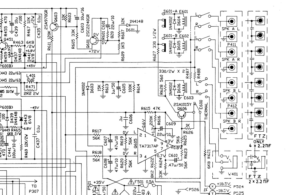
The NAD 7100 loudspeaker protection circuit
Power Envelope - Power On Demand - Powerdrive
Power driving the NAD 7100
Q443, Q447 and Q451 form the heart of the beast. Do you recall that these are very high voltage output transistors? Q443 feeds the output transistor Q439 with a voltage jump from +44.4V upwards, blocked by diode D433. No, the amplifier is not designed to run on +/- 72V to the output pair but rather the supply rail voltage is shifted according to demand of power power requirement. Proton came up with Power on Demand hype, not surprising since they used to build NAD under licence years back. This where things can become interesting – D443 may be prone to failure. This will cause a host of problems – protection relays may kick in because of imbalance in the power supply rail but I would be checking zeners D441 and D443 first. Replacements for D443 should be designed for a beating – fast switching and high current with a minimum 100V PIV rating. Whether they go faulty I would not know but like all things electronic I’d be looking there. This is after all a high powered amplifier, don’t be fooled by the 50/60W rating.
Some topics of interest
Do read up on the TA7317AP IC. Many amplifier designers used other circuits to protect DC from loudspeakers but this is a dedicated chip and very, very popular. Knowing why the amplifier protection is on (or loudspeaker protection) is fundamental to a good repair. Sadly, usually all pointing to the output and driver transistors (except in my case, the moisture residue left in cleaning off dust with compressed air).
Preamplifiers are known to cause problems but are usually related to capacitors and switching circuitry. For another day.
To sum up
- Audio power amplifiers go faulty for a number of reasons, sometimes not obvious to the owner/user.
- Get a schematic. Understand the schematic. I don’t always but as long as you have a general idea what to look for then you are on the right track.
- Get a scope if you are planning to take this the full distance. Use a good quality meter – Fluke is a good make and you won’t go wrong. There are others out there as well – the U$10.00 variety has it’s limitations.
- High current, high voltage, high energy circuits are usually where the problem starts.
- Do not switch on without a form of protection – 10 Ohm 5W resistors across the fuse holders will assist in many ways – this is often used as ‘cheap protection’ by designers. Lightbulbs with TV repair.
- If you can afford it, get a variac. Not Viagra.
- Insulate your probes down to a 1mm playing field. I was involved in electronic repair for many years, impatience is one of the biggest causes of further damage – worse still, time wasting. The thinker, the plodder fixes faster than Billy Whizz.
- If something doesn’t feel right, it isn’t.
Getting back to the NAD 7100
- These amplifiers are getting on in years now – electrolytic capacitors will be found with low ESR (equivalent series resistance). It’s not a big job, replace them all if you are doing restoration.
- The output transistors are very expensive – if they are still fine then make sure they stay fine. Probing around on a live circuit is inviting problems.
- Your mid rail at the emitters of the output devices is the first thing to check after the power supply rails have been found to be within spec.
- Feel temperature of heatsink.
- Smell.
Do NOT give up. These are great amplifiers but when it comes to repair, service technicians charge for their time. What they rate as a waste of time is based on their repair time – not yours. The biggest let down is told not to do it, you can get a second hand one on eBay for ‘x’ dollars. Certainly – but do you know that in a few months time you may be in the same boat. The 7100 makes a great mono block (I hate the term). Buy another one if you want two – but then get the 2100 which is the same amplifier without the receiver.
If you are going to dump have you checked the mains transformer? Is it working? Mains transformers of this VA rating are very expensive. More so, mains transformers of the VA rating AND output voltages are very expensive.
Lastly, I find many of the responses on the forums based on hearsay. I have no experience with the 7100 because when I was repairing equipment this was still a new kid on the block and most would have been under warranty. I hear that NAD had more problems than any other amplifier – strange this because my first NAD experience was with a NAD 1020 pre-amp. One channel was dead. It did not leave a great feeling – the salesman was an absolute dingbat. But NAD will prevail, they do have a sound quality which many people find fulfilling. They are under-rated and for their price are difficult to beat. NAD amplifiers sound great with Mission or AR speakers. They are designed to play into any load known to man.
I hope my outlook at the repair of this amplifier may be of some assistance. If not, please mail me at webmaster parts ring – I will gladly you give any assistance that you may require. Please do not expect an immediate reply, neither for me to assist without schematics. This can be tedious and time-consuming but in most cases the amplifier can be repaired without the schematic – I get a lot of requests for schematics but as a general rule most audio amplifiers follow conventional class AB amplifier design. When in doubt go to ESP and read. Read a lot 🙂 – Elliott Sound Products.
Return to Main Page – Repairing the NAD 7100 Receiver