Table of Contents
ToggleTools of the Trade – The Heavy Iron
Electronic Workhorses
In our previous posts, we talked about the physics of the sky and the math of the signal. But on the bridge of a Merchant Navy vessel, physics and math had to be housed in steel.
As a Radio Officer, your gear was your lifeline. If you were sailing with Marconi or JRC (Japan Radio Co.), you weren’t just using a radio; you were commanding a masterpiece of industrial engineering.
The Marconi "Commandant" & "Conqueror" Transmitters

For those of us on British-flagged or Commonwealth ships, the name Marconi Marine was everywhere.
- The “Commander” Transmitter: This was a 400W PEP (Peak Envelope Power) transmitter, the baby brother of the Conqueror – see below. (The Commandant was the transmitter that radio students were required to fault-find at the Cape Technikon, Cape Town. Lecturers were Henry Pasman and Albert Vianello who made his debut by being the Sparky on the S.A. Seafairer when she ran aground).
The “Conqueror” Transmitter: This was the beast that handled the 1500W PEP we discussed. Because SSB requires linear amplification, these transmitters used massive power tubes (valves) running in Class AB, capable of delivering varying power levels depending on the frequency band and mode of operation:
- HF (High Frequency, 4–25 MHz): The transmitter reached its peak performance here, providing up to 1,500 watts on 4 and 6 MHz for A1 (CW) and A3J (SSB) modes. This power level slightly decreased on higher bands, falling to 1,100 watts at 22 MHz and significantly dropping to 200 watts on the 25 MHz band.
- MF (Medium Frequency, 405–525 kHz): Power was lower in this range, typically 500 watts for A1 mode and 320 watts for A2H mode.
- IF (Intermediate Frequency, 1.6–3.8 MHz): Power was limited to 400 watts PEP (Peak Envelope Power) for all emissions.
The unit was known for its robust construction, requiring approximately 3.9 kVA of input power from a 3-phase AC source. Its design was so powerful that operators often noted the power amplifier (PA) valve anodes should glow “cherry red” during proper tuning.The Heat: To get that 1,5kW out to the antenna, the rig was drawing nearly 3kW of DC power. The radio shack was often the warmest room on the ship, smelling of heated dust and high-voltage transformers.
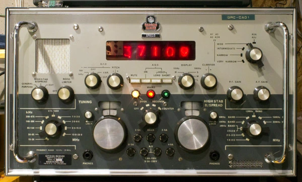
The “Apollo” Receiver: A marvel of stability. When you were pulling a weak signal from a station halfway across the globe, the Apollo’s frequency synthesis was the gold standard.
The JRC Revolution
When Japanese engineering, specifically JRC, began to dominate the market, we saw a shift toward incredible integration.
Solid State Transition: JRC was a pioneer in moving away from the “warm-up time” of tubes toward the instant-on reliability of high-power transistors.
The “NSD” Series: These rigs were legendary for their ergonomic layout. Everything was where it should be. For an officer working a 12-hour watch, the ease of use and the clarity of the JRC filters were a godsend.
The "Class AB" Reality
As we studied at Cape Technikon, which had the only “radio school” in South Africa, the move to SSB meant we could no longer use the high-efficiency Class C amplifiers used for Morse (CW). To keep the voice signal from distorting (becoming “splatter”), we had to use Linear Amplifiers.
The Technician’s Note: Yes, we were “wasting” power as heat in the amplifier stages, but because we had suppressed the carrier, every single watt of that 1500W PEP was working to carry your voice. On the old DSB rigs, you might have a 400W carrier and only 100W of actual voice power. The math was clear: SSB won every time.
The Anatomy of the Shack
Behind every dial was a “Ring” of essential components that kept the ship on the air:
High-Voltage Capacitors: Built to withstand the massive peaks of a linear amp.
Ceramic Tube Sockets: Designed to dissipate the heat of those 3kW power draws.
The Dummy Load: A massive resistor submerged in oil, allowing us to tune the transmitter to full power without radiating a signal across the entire ocean.
Why this matters at Parts-Ring.com
We respect the “Heavy Iron.” We understand that in the maritime world, “good enough” isn’t an option. Whether it’s a high-current relay or a precision transistor, we source parts that would have passed a Marconi inspection.